Flat roof drainage: Focus on safety and sustainability
Knowledge for MEP planning
Flat roofs have numerous advantages, but they have to overcome an enormous structural challenge. During planning and execution, the topics of safety, fire protection and thus the question of roof drainage have top priority. ACO offers functional solutions that are specially tailored to the flat roof application and ensure optimal drainage of rainwater. For smaller areas, gravity drainage systems are suitable. On large roofs of around 150 m² or more, drainage systems with negative pressure are preferred. ACO offers products in stainless steel, galvanized steel and cast iron. There are also special solutions for green roofs, parapets and emergency drainage.
ACO supports you in the planning of right flat roof drainage and the hydraulic calculation for the siphonic drainage system with the latest, standard-compliant design software and a high level of practical knowledge.
Contents
The use of flat roofs is becoming increasingly versatile: they serve not only as parking spaces, but also as roof terraces,
sports or play areas, and even parks. Green roofs in particular make an important contribution to balancing
sealed surfaces. Due to these diverse uses, the requirements and regulations vary considerably. There is therefore no universal standard for the use of roof areas; instead, various specific guidelines and regulations must be observed. The safe design of flat roof drainage is the responsibility of the architects and building services engineers and must be carried out in a manner appropriate to the respective roof construction.
Design of flat roof drainage
The drainage calculation is based on the specifications of EN 12056-3‘Gravity drainage systems within buildings’ and DIN 1986-100‘Drainage systems for buildings and properties’.
Planning, execution and maintenance of flat roof drainage
Specific requirements and technical specifications for the waterproofing of roofs and similar components are laid down in DIN 18531 ‘Waterproofing of roofs, balconies, loggias and pergolas’. This standard is particularly relevant for the planning and implementation of waterproof outdoor areas and roof structures. In addition, DIN 18532 ‘Waterproofing of concrete traffic areas’ should also be mentioned here. This deals with so-called top decks, i.e. flat roofs that are accessible to vehicles. Architects and planners also refer to the flat roof guidelines, which are issued as technical rules for waterproofing by the Central Association of German Roofers (ZVDH) as recommendations. Information on maintenance can be found in DIN 1986-3.
Dimensioning of the drainage system
Another decisive factor for the dimensioning of drainage systems is the local rainfall, which is determined in accordance with local standards (local rainfall database etc.). This data provides information about the expected precipitation amounts in the respective region and is therefore decisive for the design of drainage capacities. Local regulations often take into account region-specific conditions and requirements, to ensure that the drainage systems are sufficiently dimensioned to cope with the expected rainfall amounts.
| Selection of the drainage system | ► | Relevant for planning | ► | Requirements for the product |
|---|---|---|---|---|
|
|
|
All ACO flat roof gullies comply with the relevant standards, are manufactured in accordance with these standards and thus guarantee the highest standards of safety and quality.
Flat roof gullies collect rainwater from flat roofs, parking decks, green roofs and terraces. The rainwater is then drained away via drainage pipes. There are two basic types of flat roof drainage systems: gravity drainage and siphonic drainage. → Decision diagram
Siphonic drainage
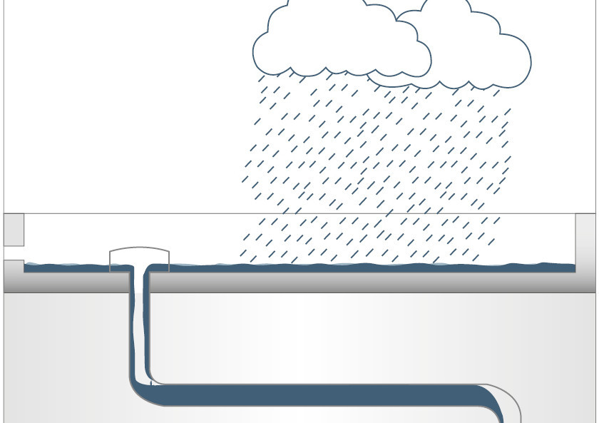
Siphonic drainage is a system for draining rainwater from roof surfaces, which is characterized by the creation of negative pressure in the collection pipes. In accordance with DIN 1986-100:2016-12, the drainage flows from individual roof gullies are fed through connection pipes below the roof structure to a central downpipe. The resulting negative pressure enables rapid drainage of the roof surface by drawing the water through the system at high flow velocity. One advantage of siphonic drainage is the possibility of laying the pipes below the roof without a slope, which allows for flexible room design and use. The full filling of the pressure pipe system also achieves a high flow velocity, which promotes self-cleaning of the pipe system and reduces maintenance costs.
Siphonic drainage works with special flat roof gullies which, in contrast to gravity drainage, are operated with pipes that are filled to capacity (filling ratio h/d 1.0). In order to achieve this full filling, the entry of air (air suction) must be prevented when rainwater enters the pipe. As soon as the design rainfall required for operation is reached, the system operates with fully filled pipes in the pressure flow range, which means that the connected roof area is drained quickly and safely. However, this also means that as long as only light rainfall occurs, the systems operate as gravity drainage if the backwater required for operation cannot be reached.
Gravity drainage
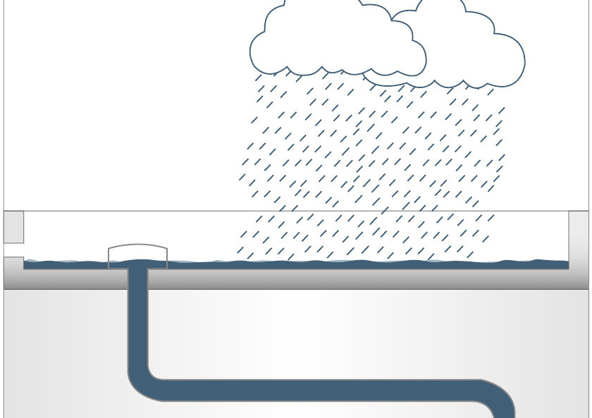
Gravity drainage is a drainage system based on the principle of gravity to drain rainwater from flat roofs, terraces and similar surfaces. In this system, the water flows freely, without negative pressure, through the flat roof gullies and the connected pipes. The efficiency of gravity drainage depends largely on the correct dimensioning of the pipe diameters, which are calculated in accordance with the standards DIN EN 12056-3 and DIN EN 1986-100.
A characteristic feature of gravity drainage systems is the large number of gullies connected to a downpipe via a collecting pipe or directly to the downpipes, which requires a sufficient gradient and a corresponding number of connections to the underground pipes to ensure effective water drainage. For gravity drainage systems in accordance with DIN EN 12056-3 (installed inside buildings), the filling ratio (h/d) must not exceed 0.7 (horizontal pipe) or 0.33 (vertical pipe), as only up to this value can sufficient ventilation of the pipes and thus safe drainage of rainwater be guaranteed.
Emergency drainage
- Roof gullies on flat roofs in accordance with DIN EN 1253-2 must be dimensioned for regular operation (standard operation) up to specified accumulation heights.
- Any precipitation exceeding the calculated rainfall can lead to accumulation on the roof surfaces. However, additional accumulation on the flat roof can lead to damage to the roof structures or to uncontrolled flooding of the areas below. Therefore, these additional amounts must usually be drained via specially designed drainage systems, known as emergency drainage systems.
- Emergency drainage systems are mandatory for lightweight roofs, and for roofs with green roofs, static verification must be provided for the emergency drainage system, taking into account the target water depth. (DIN 1986-100)
Emergency drainage systems are an essential component of modern rainwater drainage systems, especially when it comes to coping with extreme weather events such as once-in-a-century rainfall. Emergency drainage must not be connected to the sewer system. According to DIN 1986-100, it must be directed to a property area that can be flooded freely and without damage. Discharge would place an additional burden on the sewers.
In order to protect their sewer systems from hydraulic overload, local authorities can also impose discharge restrictions on roof drainage. Whether these discharge restrictions must be taken into account in planning can be found in the sewage regulations. Every low point must have an emergency gully in addition to the standard gully. Emergency drainage must be planned for flat roofs; it can only be dispensed with if there is static proof of the load-bearing capacity of the roof area and if it is used for rainwater retention as planned. Emergency drainage can be provided by emergency gullies or emergency overflows.
Emergency drainage can be implemented by means of additional emergency gullies or parapet gullies, which are designed to activate when a critical water level is reached and drain off the excess water. Waiving emergency drainage is only justifiable for solid roofs with static proof. These can be, for example, roofs with planned rainwater retention. However, these usually have gullies with an integrated overflow system to minimise the risk of overloading the roof structure.
When planning drainage for flat roofs, there are a few basic considerations to take into account to ensure that rainwater is effectively drained away. The number and type of gullies required depend on the size of the roof area, the roof construction and local rainfall conditions. Different roof materials and structures, such as concrete, gravel or green roofs, influence how much water actually drains away. This is taken into account by the drainage coefficient. Rainfall, i.e. the amount of rain expected in a region, also plays an important role in the dimensioning of drainage systems.
Calculation of rainwater volumes
When planning drainage systems for flat roofs, it is crucial to calculate the exact amount of rainwater (QD for standard drainage and QD,Not for emergency drainage). These calculations are based on equations (1) and (2) and can be applied to all exposed surfaces such as roofs and roof terraces.
(1) QD = r(5,5) ⋅ C ⋅ A ⋅ 1/10.000 (in l/s)
(2) QD,Not = (r(5,100) − r(5,5) ∙ C) ∙ A/10.000 (in l/s)
Standard drainage
The calculated rainfall intensity r, expressed in l/(s ∙ ha), is a statistical value provided by local standards that indicates the expected amount of rainfall per second and hectare. According to DIN 1986-100, a rainfall duration of 5 minutes is used for the design, with a return period of 5 years for standard drainage and 100 years for emergency drainage.
The peak runoff coefficient C takes into account the proportion of rainwater retained by the roof structure and the proportion that must be drained away by the drainage system. For gravel surfaces, this value is 0.8, which means that 20% of the water is retained and the standard drainage system can be dimensioned accordingly smaller.
Emergency drainage
Emergency drainage is dimensioned larger than standard drainage in order to account for the difference between standard and emergency drainage. The peak runoff coefficient is first multiplied by the rainfall intensity for standard drainage, and this product is then subtracted from the rainfall intensity for emergency drainage. The area A of the flat roof, expressed in m², is decisive for the calculation and must be assumed to be the area projected in the roof plan. The rainfall intensity, peak runoff coefficient and area factors are divided by 10,000. The divisor is derived from the conversion factor from ha to m² and is 10,000. Gravity drainage is usually sufficient for residential and office buildings. Siphonic drainage systems are specially designed for situations with large amounts of rainwater and extensive roof areas.
Siphonic drainage: Planning support from our application engineers
Our team will assist you with your roof drainage, including calculation, planning and dimensioning of the waste water pipes.
Consulting on the design of flat roof drainage systems
Design of siphonic drainage
Project planning for piping and drainage requirements
Dimension and type of flat roof drainage systems
When planning the drainage of a flat roof, the size and type of gullies must be carefully selected. This decision depends on the amount of rainwater that needs to be drained from the roof, as well as the number of gullies required and the condition of the roof itself. To determine how many gullies are needed, divide the amount of rainwater (Q) by the drainage capacity of a single gully (QDA), which is specified by the manufacturer. This capacity indicates how much water the gully can handle and is often higher than the minimum standard specified in DIN EN 1253-2.
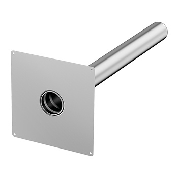
It is important to note that every low point on the roof, i.e. every point where water could collect, must have at least one regular gully or one emergency gully. In roof valleys, the lines where two roof surfaces meet, the gully should not be more than 20 metres apart. The choice of gully, including the top part and the accessories, depends on the roof construction and roof layers. The gullies are usually supplied with a press seal or adhesive flange for attaching the sealing membranes. A width of at least 100 mm is required for adhesive flanges. According to DIN 18531, the distance between gullies and walls or other upright components should be at least 30 cm for membrane-type waterproofing. When using liquid sealants, this distance should be at least 10 cm, but this does not apply to parapet gully.
Discharge restrictions
Local authorities are increasingly imposing discharge restrictions in order to reduce the load on the sewer system and minimise the risk of flooding. Some reasons for these restrictions are:
- Climate change: Climate change is leading to an increase in extreme weather events with heavy rainfall. This can exceed the capacity of drainage systems and lead to flooding.
- Sealed surfaces: Sealed surfaces in cities due to increasing development prevent rainwater from seeping into the ground. Instead, more water flows directly into the sewer system, which increases the load on it.
- Environmental protection: Delaying the discharge of rainwater into the sewer system reduces the risk of mixed water overflows into natural water bodies. This protects the environment from pollution by untreated wastewater.
- Sustainable water management: Discharge restrictions promote the use of sustainable water management measures, such as rainwater harvesting or the installation of green roofs, which help to reduce direct runoff and increase biodiversity.
Rainwater retention with green roofs
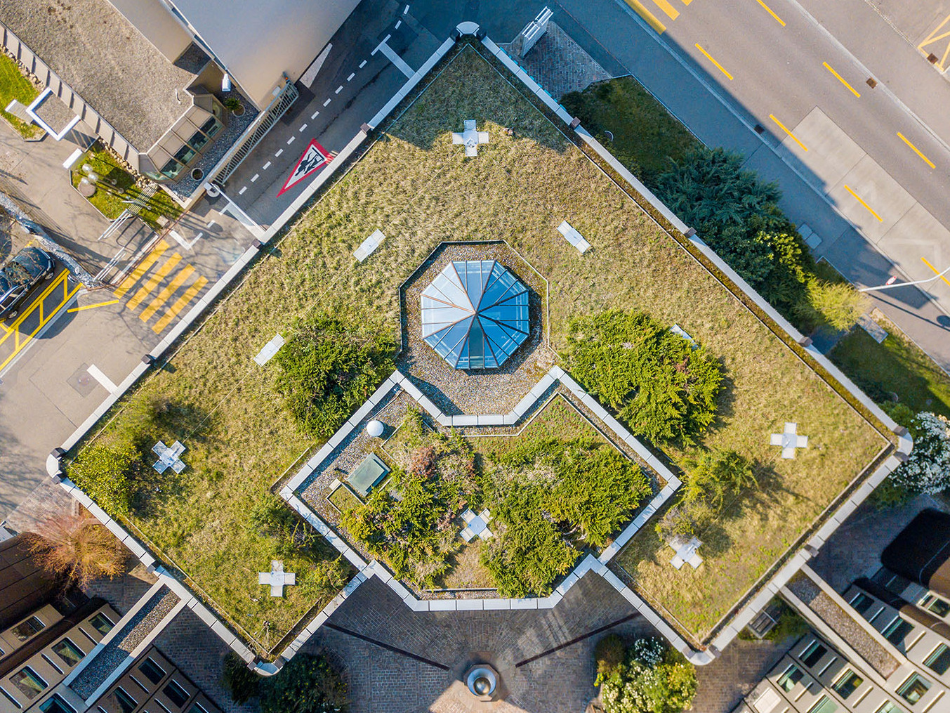
Green roofs are an effective solution for storing rainwater and reducing direct water runoff. They not only contribute to delayed rainwater runoff, but also improve biodiversity and the microclimate, especially in urban areas. However, additional aspects must be taken into account when planning a green roof. These include the additional load caused by the vegetation and the need for root-resistant roof waterproofing. In the case of tall or particularly wind-prone buildings, wind suction load and drift resistance must also be taken into account.
Greening also affects roof drainage. The peak runoff coefficient, which takes the roof structure into account, and an effective drainage layer are crucial for the correct drainage of rainwater. Rainwater management refers to the sustainable use of rainwater. Roof drainage can make a valuable contribution here, but the objectives must first be defined. For example, should the roof structure in combination with the roof drainage system delay the drainage of heavy rainfall, or should the rainwater be retained on the roof to bridge dry periods? In order to implement these requirements in practice, drainage systems with retention attachments have proven effective. Their special perforation allows part of the rainwater to be drained with a time delay or to remain on the roof. In combination with discharge restrictions, green roofs, in conjunction with coordinated drainage, offer a sustainable solution for rainwater management that brings both ecological and urban planning advantages.
To protect the roof gullies from root penetration, DIN 1986-100 recommends a 50 cm wide gravel strip with a grain size of 16/32, as specified in the flat roof guideline.
Is it possible to drain water onto the roof terrace?
When planning drainage for flat roofs that transition into surrounding roof terraces on staggered floors, the question often arises as to whether rainwater from a flat roof may be directed onto an adjacent terrace. In general, this is possible, especially if the water flows from a smaller to a larger area, which complies with DIN 1986-100 and is permitted in exceptional cases. In areas where the water hits, reinforcement of the waterproofing or roof covering may be necessary. According to DIN 18531, additional water volumes from higher roof areas must be taken into account in the planning. However, cascade drainage carries risks, such as water entering the building, especially if the maintenance of the roof gullies is neglected and there are barrier-free transitions to the roof terrace. From a planning and regulatory perspective, it is more appropriate to drain rainwater into pipes or flat channels instead of directing it to an area below. The specifications for the slope of flat roofs can be found in the Flat Roof Guideline and DIN 18531. A minimum slope of 2% is recommended to prevent puddles from forming due to structural deflection or unevenness. A slope of 5% or more can be assumed to result in a puddle-free surface. Roofs in application class K1 can be designed without a slope, provided that the waterproofing meets the higher requirements of application class K2. For roofs in application class K2, in addition to the minimum slope, a slope of 1% in the valleys is recommended.
Fire protection for flat roofs
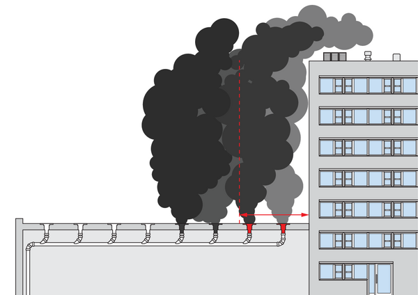
Flat roof gullies are important components of the roof structure, enabling water to drain from the roof into the interior of the building. However, in the event of a fire, there is a risk that toxic fumes and smoke could escape upwards through these gullies and enter neighbouring buildings located higher up, for example through windows or doors.
To minimise this risk, national building regulations stipulate the use of special fire protection flat roof gullies, especially if the distance between a roof gully and a wall is less than five metres. These fire protection gullies are specially designed to prevent the spread of fire and smoke, but they are not standard construction products and therefore require general building approval and general type approval.
In certain situations, such as when flat roofs serve as escape routes, it may be necessary to install fire protection gullies to ensure safety, regardless of the distance to the wall. These gullies are equipped with fire protection devices that prevent the spread of fire and smoke. It is important that the fire resistance class of the roof gully is at least equal to or higher than that of the roof ceiling in order to ensure optimum protection.
Local building regulations
State building regulations require the use of flat roof gullies with appropriate fire protection measures if the distance between roof gullies and an ascending wall (with openings or without fire resistance) is less than five metres in these areas.
Fire resistance class
In addition to the fire protection inserts, the gully themselves must also have a fire resistance class (R). In addition to the fire resistance class (R), the same classification also exists for building ceilings, which begins with the letter ‘F’ instead of the letter ‘R’. The fire resistance of F90 for a building ceiling is therefore 90 minutes.
| Fire resistance duration | Building authority designation | Fire resistance class (R) for pipe insulation | Fire resistance class (F) for room-enclosing components |
| 30 Minutes | fire-proof | R30 | F30 |
| 60 Minutes | highly fire-resistant | R60 | F60 |
| 90 Minutes | fire-resistant | R90 | F90 |
| 120 Minutes | highly fire-resistant | R120 | F120 |
ACO´s Solution
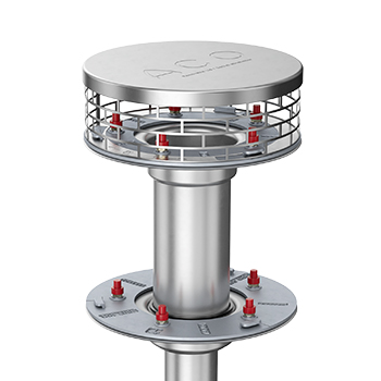
Stainless Steel Flat Roof Drainage System
- Modular system for gravity and siphonic drainage
- Additional components for green roofs
- Siphonic drainage: Suitable for large roof areas of 150 square metres or more
- Can be used as emergency drainage
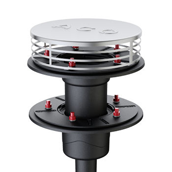
Cast Iron Flat Roof Drainage System
- Flat roof gully for siphonic pressure and gravity drainage
- Additional components for green roofs
- Long-term resistance to weathering
- Fire protection: cast iron offers a high level of safety
- Support from planning to execution
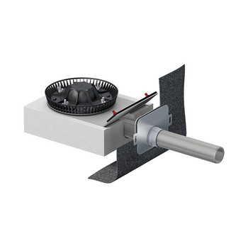
Attic Stainless Steel Roof Drainage System
- Modular system for gravity or siphonic drainage
- High-quality stainless steel (1.4301) for durability
- Available in DN 50, DN 70, DN 100
- 45° upstand for bitumen or 90° upstand for plastic sealing membranes
ACO Pipes
- Stainless steel ACO pipe system
- Designed for gray and black water, rainwater and industrial waste water drainage applications
- Suitable for both siphonic, vacuum and gravity drainage solutions
- Double lip seal push-fit connection for easy and reliable installation
- Resistant to thermal and dynamic shocks
- Fast, reliable and cost-effective installation
- Sagging-proof, non-combustible, rodent-proof
Roof application engineering
Do you need support with planning and calculations? Get in touch with us – we’re here to assist you with the design of your roof drainage system.


